T-SENSOR
Contactless torque sensor
for power transmissions

Taking a look at classic solutions
„Classical“ torque sensors always require, that the shaft to be measured must be: either divided to insert a special flange or strain gauges and electronics be applied to the shaft in a challenging procedure.
Leading us to significant disadvantages
- Significant maintenance
- Specially trained staff needed
- Frequently outages
The Solution: T-Sensor
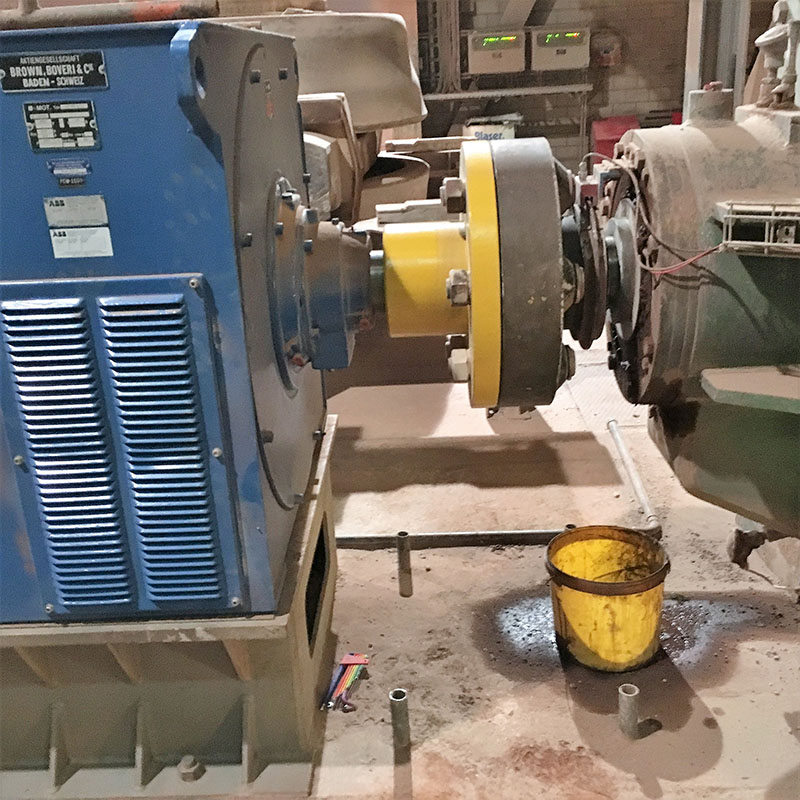
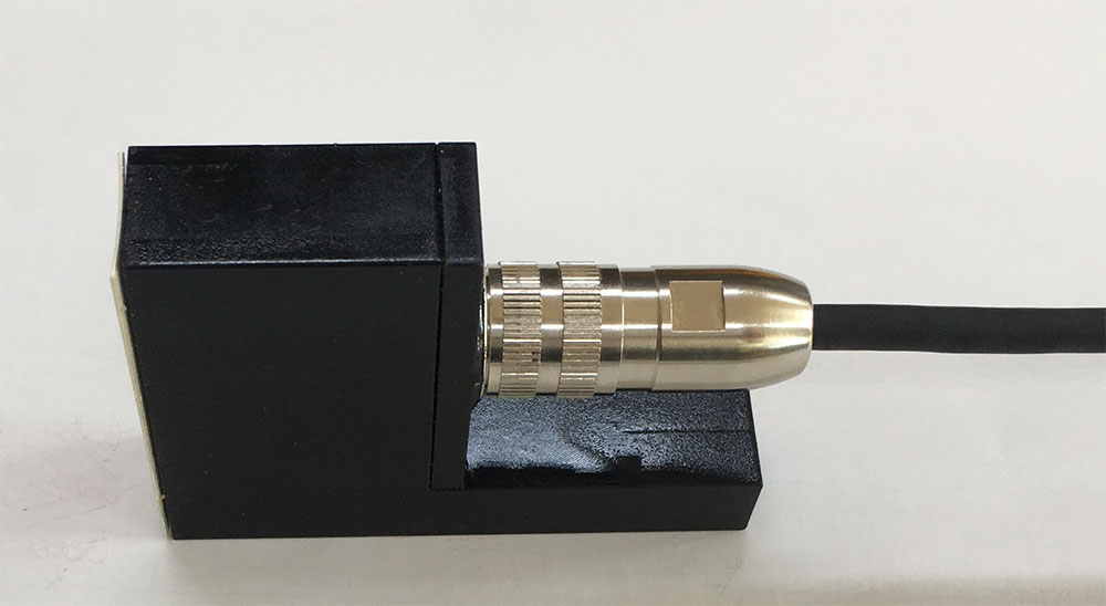
This can be completely avoided, by using our magnetic Torque-Sensor “T_Sensor”. The sensor head only needs to be positioned in close proximity to the shaft (0.5 . . . 3 mm). No division of the shaft or application of any sensing element on the shaft is required.
Benefits
- Contactless principe
- Dicatance between sensor and shaft in the range of a few millimeters
- Application in dirty, abrasive or aggressive environment
- No limitation with respect to the shaft diameter
- No magnictic hysteresis effects
- No temperatur drift
Functional Principle
The patented ARGUS sensor does not require any treatment or any alteration of the measurement object. The sensor head consists of several inductances. The transmitter coil is fed by an electrical current of a constant frequency. The equidistant located receiver coils act as a passive part of the sensor. The detection of torque- or speed-dependent phase shifts between the input and the received signals are accomplished by an innovative sensor electronics. The underlying analysis software reduces drift and interference effects for instance caused by thermally driven effects or material-specific hysteresis effects.
Moving domain walls in a grain of silicon steel caused by an increasing external magnetic field in the “downward” direction, observed in a Kerr microscope. White areas are domains with magnetization directed up, dark areas are domains with magnetization directed down.
Zureks, Chris Vardon, Moving magnetic domains by Zureks, CC BY-SA 3.0
Measurement of Torsional Load
The elastic and reversible deformation of a solid body is de-scribed by Hook’s law. Any force applied on a deformable body manifests itself in a geometrical change in its dimensions. A torsion-loaded homogeneous and cylindrical-symmetrical body thus experiences a mutually deforming state, which develops along the tensile and compressive stress lines. This stress-induced deformation state causes a variation in the magnetic properties of the ferromagnetic material. In magnetic materials without any preferential direction (untreated axes made from steel and shafts without functional layer), a mechanical stress state leads to a decline of the magnetic susceptibility. A mag-netic field applied to a ferromagnetic material will follow the electro-mechanical induced changes in the material.
Measurement of the shaft speed
The interaction between an electrically conductive and moving body (axle/shaft) with an externally applied magnetic field leads to an induction of electrical currents in a material. These induced electric currents cause an induced magnetic field, which is superimposed on the applied field and thus changes in amplitude and phase. The change in amplitude or phase is proportional to the rotational speed of the wave in the magnetic field.
Measurement of displacement and oscillations
The relative change in the distance between the measured shaft and the sensor manifests in an increase or decrease of the applied signal intensity. This change can be evaluated as it is realized by conventional inductive proximity sensors. Since the external magnetic field excitation is provided by a temporally periodic current, the distance change or tilt of the measurement object can also be represented as electrical amplitude or phase change in the receiver coils. The increase of the excitation frequency as a function of the circulating frequency of the measuring object therefore also opens the way for the realization of an inductive oscillation analysis.
Datasheet
Shaft
diameter
50 mm…open (parameter)
distance sensor
1 mm…3 mm
Torque
range
0 kNm…open (can be parameterized)
resolution
~ 1 % of max. torque
Speed
range
0…1500 RPM
resolution
< 1 % of max. speed
Time resolution
200 Hz
System is calibration free, if material, diameter and distance are known
